Friday, July 10, 2009

Energy Storage Element Stamps for Transient Analysis

As was mentioned before, a DC analysis is performed prior to transient analysis to get the solution at t = 0. During this DC analysis, coils and capacitors for which no initial conditions were specified are replaced by short circuits and open circuits respectively, while coils and capacitors for which initial conditions were specified, are replaced by infinite-impedance current sources and zero-impedance voltage sources respectively.
Also, at each time point after t = 0, each energy storage element is replaced by its companion model.

This means that, to perform transient analysis, three matrix stamps are needed for each energy storage element:

  1. A stamp to be used at t = 0 if no initial condition is specified.
  2. A stamp to be used at t = 0 if an initial condition is specified.
  3. A stamp to be used at t > 0.

I found that the computer implementation of transient analysis will be greatly simplified if

  1. The three stamps for an energy storage element have the same size.
  2. The index of an excess unknown points to the same excess unknown in the three stamps.

We should have these two conditions in mind while choosing the equivalent circuits for energy storage elements.

The Capacitor Stamps

Capacitor

1) At t = 0 / no IC specified

CapacitorStampTZeroNoIc 
The dashed line in the figure above separates the node equations from the excess equations, and the node voltages from the excess unknowns.

2) At t = 0 / IC specified

CapacitorStampICSpecified
The dummy resistor between node plus and the internal node is added just to make the coefficients matrix nonsingular.

3) At t > 0

CapacitorStampTGreater  
Note that in the three cases the stamp has a the same size, the first excess unknown index points to the internal node voltage, and the second excess unknown index points to the capacitor current. So the two conditions stated above are satisfied.


The Inductor Stamps

Inductor 
1) At t = 0 / no IC specified

InductorStampTZeroNoIc  
2) At t = 0 / IC specified

InductorStampIcSpecified
3) At t > 0

InductorStampTGreater  

The Transformer Stamps

Transformer 
1) At t = 0 / no IC specified

TransformerTZeroNoIC 
Stamp of the primary coil

PrimaryTZeroNoIC
Stamp of the secondary coil

SecondaryTZeroNoIC
2) At t = 0 / IC specified

TransformerTZeroICSpecified 
Stamp of the primary coil

PrimaryTZeroICSpecified 
Stamp of the secondary coil

SecondaryTZeroICSpecified 
In the previous two cases, I gave two separate stamps for the primary and the secondary rather than one big stamp for both of them because the user may specify an initial condition for one coil and leave the initial condition for the other coil unspecified.

3) At t > 0

TransformerTGreater

Thursday, July 9, 2009

What Makes a Circuit Element an Energy Storage Element?

The constitutive equation of a circuit element is a relationship imposed by the element on the solution of the circuit.

If the constitutive equation of an element does not depend on the state of the element at previous time points, then this element is a memoryless element. For example the constitutive equation of a resistor at time t is v(t) = i(t) * R. This is clearly independent of the voltage across and the current through the resistor at any time before t. This makes the capacitor a memoryless element.

Conversely, if the constitutive equation of an element does depend on the state of he element at a previous time point, then the element is an energy storage element and does have memory. Equations (1), (2), (3) and (4) in the previous post show that the inductor, the capacitor, and the transformer are energy storage elements because their constitutive equations at time t + 1 depend on their state at time t.

Companion Models

The Capacitor’s Companion Model

Capacitor

At any point in time, the equation relating the capacitor voltage to the capacitor current is

CapacitorTimeDomainEquation

This equation is not very useful because it will cause terms with dbyd to appear in the Modified Nodal Analysis (MNA) equations. We do not have a computer method for solving sets of linear differential equations. We can only solve sets of linear algebraic equations (remember the triangular decomposition algorithm and our LinearEquations class).

We will combine the trapezoidal rule with the capacitor’s differential equation to get a linear algebraic equation relating the capacitor voltage to the capacitor current.
The differential form of the trapezoidal rule is

TrapezoidalRule
We will now replace the generic variable (x) by the voltage across the capacitor (v).

CapacitorSubstitution

Substituting into the trapezoidal rule equation

CapacitorCompanionModelEquation

Equation (1) says that the relation between the capacitor voltage and the capacitor current at time t + Δt depends on the capacitor voltage and the capacitor current at time t. This means that the capacitor (like other energy storage elements as we will see later) has memory.

Two circuits that satisfy equation (1) are shown in the following figure.

CapacitorCompanionModel
These equivalent circuits are called companion models.

The solution at time t is used to build the companion models that will be used to solve the circuit at time t + Δt. After building the companion models, DC analysis is performed to get the solution at time t + Δt. The time is then advanced again and the solution at t + Δt is used to build the companion models for the next time point.
The first transient step depends on the initial conditions to build its companion models. The initial conditions can be specified by the user. The unspecified initial conditions are obtained from DC analysis performed prior to transient analysis.


The Inductor’s Companion Model

Inductor
At any instant, the inductor I-V relationship is given by

InductorEquation
Remember the trapezoidal rule

TrapezoidalRule
This time we substitute x by the capacitor current (i).

InductorSubstitutions

Substituting in the trapezoidal rule

InductorCompanionModelEquation
The two companion models that satisfy equation (2) are shown in the figure below.

InductorCompanionModel

The Transformer’s Companion Model

I could not find the transformer’s companion model anywhere, so I derived it myself.

Transformer
The transformer’s time domain equations are

TransformerEquations
Again, we will write the differential form of the trapezoidal rule.

TrapezoidalRule
First let

PrimarySubstitutions
Substituting in the trapezoidal rule equation we get

PrimaryEquation

Rearranging

PrimaryCompanionModelEquation
Now let

SecondarySubstitutions
Substituting in the trapezoidal rule equation we get

SecondaryEquation
Rearranging

SecondaryCompanionModelEquation
A companion model that satisfies equations (3) and (4) is shown in the figure below.

TransformerCompanionModel

Tuesday, July 7, 2009

The Trapezoidal Rule

Let a function y(τ) and two time points: t and t + Δt.

Curve

We will now make an approximation by saying that if Δt is small enough, y(τ) is approximately constant over the interval [t, t + Δt] and equal to the average of y(t) and
y(t + Δt).

TrapezoidalApproximation

Based on this approximation, the integral of y(τ) over the interval [t, t + Δt] is given by

Integral

The previous equation is the integral form of the trapezoidal rule, we will now derive the differential form which will be used in the next posts.

Let

Let 

Substituting in the integral form of the trapezoidal rule

Substituting

NoWords  
Rearranging

Rearranging

The previous equation is the differential form of the trapezoidal rule. It will be used to replace the differential equations that appear in circuits containing energy storage elements by algebraic equations.

Friday, February 27, 2009

What is Linear Transient Analysis?

Transient analysis is used to examine the response of the circuit as a function of time.
Generally, transient analysis can only be applied to circuits that are “lumped” and “time-invariant”.
Lumped means that the circuit is physically small enough to allow us to assume that electric signals affect every point in the circuit simultaneously.
Time-invariant means that delaying the input signal by a certain time simply delays the response by the same time.
The two previous definitions are from the book “Electric Circuits” by James W. Nilson.

Linear transient analysis is a special case of transient analysis where the circuit to be analyzed may only contain linear elements.

In the context of transient analysis, a two-terminal element is linear if the relationship between the instantaneous voltage across the element and the instantaneous current through the element can be described by a linear (differential) equation.
The following figure shows that the resistor, the inductor, and the capacitor are all linear elements.

TwoTerminalElements

For elements having more than two terminals, an element is linear if the relationships between instantaneous currents and/or instantaneous voltages imposed by the element can be described by a set of linear (differential) equations.
The following figure shows that the current controlled voltage source and the transformer are linear elements.

TwoPortNetworks

To conclude, linear transient analysis is used to examine the response of a linear, lumped, time-invariant circuit as a function of time.

Initial Conditions

The solution of the circuit at t = 0 must be known before performing transient analysis because the time domain solution of a circuit depends on the initial state of the energy storage elements in the circuit and also because the user may be interested in the values of some circuit variables at t = 0.

DC analysis is performed prior to transient analysis to get the initial transient solution which is the solution at t = 0.
The user may be given the option to specify initial conditions on energy storage elements (initial currents through coils and initial voltages across capacitors). In this case, the user specified initial conditions are used as constraints on the initial transient solution. Specifically, during the DC analysis, coils and capacitors for which no initial conditions were specified are treated as short circuits and open circuits respectively, and coils and capacitors for which initial conditions were specified are treated as infinite-impedance current sources and zero-impedance voltage sources respectively.

The next version of the simulator will be called Soft Analyst and will support transient analysis.

Sunday, February 22, 2009

The Formal Documentation

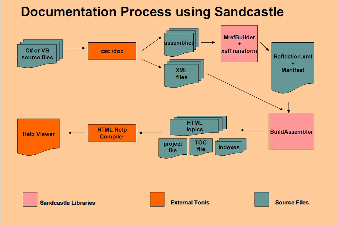
Sandcastle is a documentation tool developed by Microsoft. It generates MSDN-style documentation from

  1. the assemblies metadata obtained by reflecting over the assemblies to be documented and
  2. the XML documentation file generated by the compiler. This file contains the XML comments extracted from the source code.

Sandcastle outputs HTML pages that can be deployed to a website. It can also output a set of files that can be fed to the HTML Help Workshop to generate a compiled help file (.chm).
HTML Help Workshop is a freely downloadable HTML help compiler and is not a part of Sandcastle. You can get the HTML Help Workshop from the Microsoft Download Center.
http://www.microsoft.com/downloads/details.aspx?FamilyID=00535334-c8a6-452f-9aa0-d597d16580cc&DisplayLang=en

The following image explains a lot. I got it from a Power Point presentation I downloaded from the official Sandcastle blog.
http://blogs.msdn.com/sandcastle/archive/2006/07/28/681209.aspx


Sandcastle is an open source project hosted on Codeplex. The latest release can be downloaded from
http://www.codeplex.com/Sandcastle/Release/ProjectReleases.aspx

Sandcastle is a set of command-line programs that are hard to deal with. Luckily, there exists several community tools that provide a GUI front-end for Sandcastle. Examples of these projects are DocProject, Sandcastle Help File Builder, and Sandcastle GUI.

To generate the documentation for my BasicSimulator, I used Sandcastle, Sandcastle Help File Builder, and HTML Help Workshop.

Click here to download the formal documentation.

Thursday, February 5, 2009

The Sequence

Here is the sequence of operations from the time the program is invoked to the time it is ready to process ResQueries.
  1. The Main method loads the XML file containing the netlist. The DomParser validates the DOM and parses it to create CircuitElement objects. The CircuitElements are then packaged in a Circuit object.

  2. The Main method loads the XML file containing the analysis command. The DomParser validates the DOM and parses it to create an AnalysisCommand object.

  3. The Analyst numbers the elements that do not have an admittance description.

  4. The Analyst carries out the requested analysis.

    (A)
    If the User Has Requested
    Operating Point Analysis


    a) The circuit is formulated. Each CircuitElement is responsible for stamping its own contribution.

    b) The linear equations are solved by the LinearEquations class.

    (B)
    If the User Has Requested
    DC Sweep Analysis

    a) The circuit is formulated with the value of the variable DC source (or SweepableSource as I call it in my program) set to the starting value specified in the AnalysisCommand object.

    b) The linear equations are solved by the LinearEquations class.

    c) If the SweepableSource has attained the stopping value, then the analysis step has ended.

    d) The SweepableSource increments its value and changes its entry in the RHS vector to reflect the new value.

    e) Go to the step b.

    Note that LU factorization of linear equations will be performed only once when the equations are solved for the first time. The change in the SweepableSource value does not cause any changes in the coefficients matrix. Only one element in the RHS vector is changed.


    Steps of DC Sweep Analysis

  5. After the analysis step, the Circuit object that now contains the analysis results will be wrapped by a ResQueryProcessor object. The ResQueryProcessor object will be used by the UIManager to get the analysis results requested by the user.

  6. The Main method starts the UIManager and the interaction with the user begins.