As was mentioned before, a DC analysis is performed prior to transient analysis to get the solution at t = 0. During this DC analysis, coils and capacitors for which no initial conditions were specified are replaced by short circuits and open circuits respectively, while coils and capacitors for which initial conditions were specified, are replaced by infinite-impedance current sources and zero-impedance voltage sources respectively.
Also, at each time point after t = 0, each energy storage element is replaced by its companion model.
This means that, to perform transient analysis, three matrix stamps are needed for each energy storage element:
- A stamp to be used at t = 0 if no initial condition is specified.
- A stamp to be used at t = 0 if an initial condition is specified.
- A stamp to be used at t > 0.
I found that the computer implementation of transient analysis will be greatly simplified if
- The three stamps for an energy storage element have the same size.
- The index of an excess unknown points to the same excess unknown in the three stamps.
We should have these two conditions in mind while choosing the equivalent circuits for energy storage elements.
The Capacitor Stamps
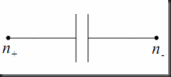
1) At t = 0 / no IC specified
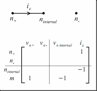
The dashed line in the figure above separates the node equations from the excess equations, and the node voltages from the excess unknowns.
2) At t = 0 / IC specified
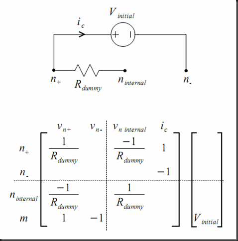
The dummy resistor between node plus and the internal node is added just to make the coefficients matrix nonsingular.
3) At t > 0
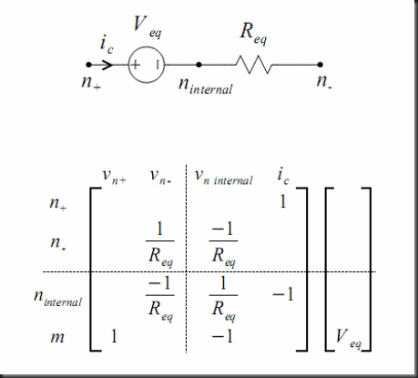
Note that in the three cases the stamp has a the same size, the first excess unknown index points to the internal node voltage, and the second excess unknown index points to the capacitor current. So the two conditions stated above are satisfied.
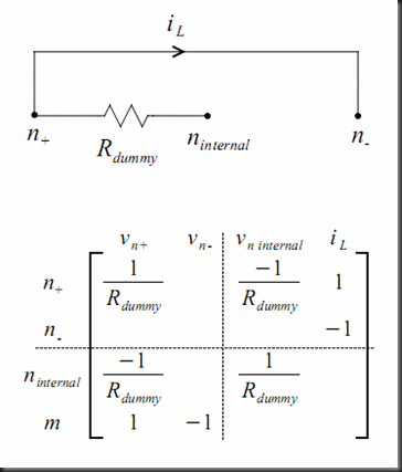
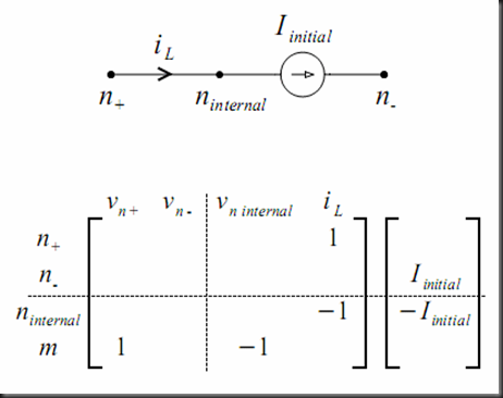
The Inductor Stamps
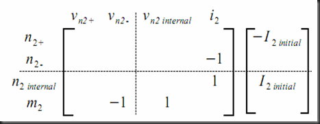
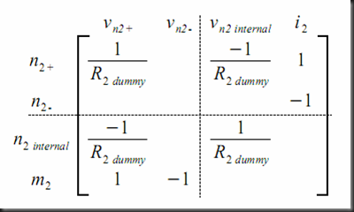
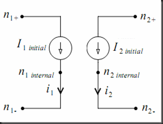
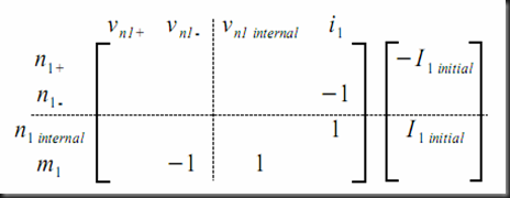
In the previous two cases, I gave two separate stamps for the primary and the secondary rather than one big stamp for both of them because the user may specify an initial condition for one coil and leave the initial condition for the other coil unspecified.
3) At t > 0




No comments:
Post a Comment